Your manufacturing client is deploying two hundred wireless IP cameras and fifty headless scanners in their warehouse. These new devices do not support 802.1X authentication.
How can HPE Aruba enhance security for these new IP cameras in this environment?
Correct Answer:
C
The best option to enhance security for the new IP cameras and scanners in this environment is C. MPSK provides for each device in the WLAN to have its own unique pre- shared key.
MPSK stands for Multi Pre-Shared Key, and it is a feature that allows different devices to connect to the same SSID with different pre-shared keys. This improves the security and scalability of the network, as each device can have its own key and role without requiring 802.1X authentication or an external policy engine. MPSK can be configured either locally on the AP or centrally on Aruba Central12.
The other options are incorrect because:
✑ A. MPSK Local is a feature that allows the user to configure 24 PSKs per SSID locally on the device. These local PSKs would serve as an extension of the base MPSK functionality. However, MPSK Local is not suitable for this scenario, as it can only support up to 24 devices per SSID, while the client has 250 devices1.
✑ B. Aruba ClearPass is a network access control solution that can perform 802.1X authentication and install certificates for devices. However, this option is not feasible for this scenario, as the new IP cameras and scanners do not support 802.1X authentication3.
✑ D. MPSK Local will not allow the cameras to share a key and the scanners to share a different key. MPSK Local will assign a different key to each device, regardless of their type. Moreover, MPSK Local can only support up to 24 devices per SSID, while the client has 250 devices1.
A customer just upgraded aggregation layer switches and noticed traffic dropping for 120 seconds after the aggregation layer came online again. What is the best way to avoid having this traffic dropped given the topology below?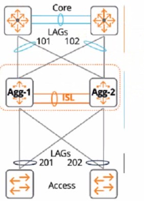
Correct Answer:
C
The reason is that the linkup delay timer is a feature that delays bringing downstream VSX links up, following a VSX device reboot or an ISL flap. The linkup delay timer has two phases: initial synchronization phase and link-up delay phase.
The initial synchronization phase is the download phase where the rebooted node learns all the LACP+MAC+ARP+STP database entries from its VSX peer through ISLP. The initial synchronization timer, which is not configurable, is the required time to download the database information from the peer.
The link-up delay phase is the duration for installing the downloaded entries to the ASIC, establishing router adjacencies with core nodes and learning upstream routes. The link-up delay timer default value is 180 seconds. Depending on the network size, ARP/routing tables size, you might be required to set the timer to a higher value (maximum 600 seconds).
When both VSX devices reboot, the link-up delay timer is not used.
Therefore, by configuring the linkup delay timer to include LAGs 101 and 102, which are part of the same VSX device as LAG 201, you can ensure that both devices have enough time to synchronize their databases and form routing adjacencies before bringing down their downstream links.
The customer needs a network hardware refresh to replace an aging Aruba 5406R core switch pair using spanning tree configuration with Aruba CX 8360-32YC switches What is the benefit of VSX clustering with the new solution?
Correct Answer:
D
VSX clustering is a feature that allows two Aruba CX switches to operate as a single logical device, providing high availability, scalability, and simplified management. VSX clustering has several benefits over spanning tree configuration, such as:
✑ Dual control plane provides better resiliency. Unlike stacking, where switches share a single control plane, VSX switches have independent control planes that synchronize their states over an inter-switch link (ISL). This means that if one switch fails or reboots, the other switch can continue to operate without affecting traffic flows or network services.
✑ Active-active forwarding provides better performance. Unlike spanning tree, where some links are blocked to prevent loops, VSX switches use all available links for forwarding traffic, providing load balancing and increased bandwidth utilization.
✑ Multichassis LAG provides better redundancy. Unlike single-chassis LAG, where all member ports belong to one switch, VSX switches can form multichassis LAGs with downstream or upstream devices, where member ports are distributed across both switches. This provides link redundancy and seamless failover in case of switch or port failure.
References: https://www.arubanetworks.com/assets/tg/TG_VSX.pdf
Refer to Exhibit:
With Access-1, What needs to be identically configured With MSTP to load-balance VLANS?
Correct Answer:
B
The correct answer is B. Spanning-tree instance VLAN mapping.
To load-balance VLANs with MSTP, you need to configure the same VLAN-to-instance mapping on all switches in the same MST region. This means that you need to assign different VLANs to different MST instances, and then adjust the spanning tree parameters (such as priority, cost, or port role) for each instance to achieve the desired load balancing. For example, you can make one switch the root for instance 1 and another switch the root for instance 2, and then map half of the VLANs to instance 1 and the other half to instance 2.
According to the Cisco document Understand the Multiple Spanning Tree Protocol (802.1s), one of the steps to configure MST is:
✑ Split your set of VLANs into more instances and configure different MST settings for each of these instances. In order to easily achieve this, elect Bridge D1 to be the root for VLANs 501 through 1000, and Bridge D2 to be the root for VLANs 1 through 500. These statements are true for this configuration:
Switch D1(config)#spanning-tree mst configuration Switch D1(config-mst)#instance 1 vlan 501-1000 Switch D1(config-mst)#exit
Switch D1(config)#spanning-tree mst 1 priority 0
Switch D2(config)#spanning-tree mst configuration Switch D2(config-mst)#instance 2 vlan 1-500 Switch D2(config-mst)#exit
Switch D2(config)#spanning-tree mst 2 priority 0
The above commands create two MST instances, 1 and 2, and map VLANs 501-1000 to instance 1 and VLANs 1-500 to instance 2. Then, they make switch D1 the root for instance 1 and switch D2 the root for instance 2.
The other options are incorrect because:
✑ A. Spanning-tree bpdu-guard setting is a security feature that disables a port if it receives a BPDU from an unauthorized device. It does not affect load balancing with MSTP.
✑ C. Spanning-tree CIST mapping is not a valid command. CIST stands for Common and Internal Spanning Tree, which is the spanning tree instance that runs within an MST region and interacts with other regions or non-MST switches.
✑ D. Spanning-tree root-guard setting is another security feature that prevents a port from becoming a root port if it receives superior BPDUs from another switch. It does not affect load balancing with MSTP.
When setting up an Aruba CX VSX pair, which information does the Inter-Switch Link Protocol configuration use in the configuration created?
Correct Answer:
D
The reason is that the Inter-Switch Link Protocol (ISLP) is a protocol that enables VSX stack join and synchronization between two VSX peer switches. ISLP uses a hello interval to exchange control messages between the switches.
The hello interval is a parameter that specifies the time interval between sending hello messages. The default value of the hello interval is 1 second. The hello interval can be configured from 1 second to 10 seconds. https://www.arubanetworks.com/techdocs/AOS-CX/10.04/HTML/5200-6728/index.html