You are configuring an SVI on an Aruba CX switch that needs to have the following characteristics:
• VLANID = 25
. IPv4 address 10 105 43 1 with mask 255 255 255.0
• IPv6 address fd00:5708::f02d:4df6 with a 64 bit prefix length
• member of VRF eng
• VRF eng and VLAN 25 have not yet been created
Which command lists will satisfy the requirements with the least number of commands?
A)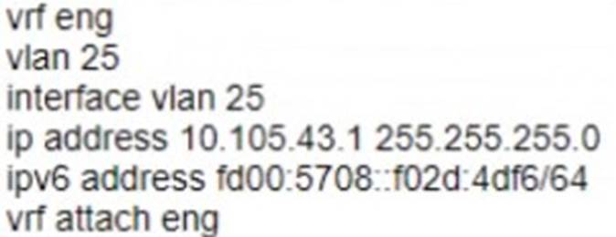
B)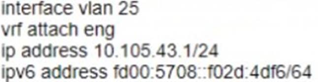
C)
D)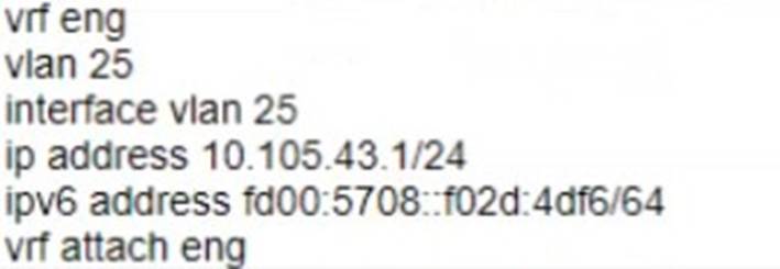
Correct Answer:
C
The other options either use more commands or do not create the VRF or the VLAN.
Option C uses the following commands:
✑ vrf eng: This command creates a VRF named eng and enters the VRF configuration mode1.
✑ vlan 25: This command creates a VLAN with ID 25 and enters the VLAN configuration mode2.
✑ interface vlan 25: This command creates an SVI on VLAN 25 and enters the interface configuration mode3.
✑ ip address 10.105.43.1/24 ipv6 address fd00:5780::102d:4df6/64 vrf attach eng: This command assigns an IPv4 address of 10.105.43.1 with a subnet mask of 255.255.255.0 and an IPv6 address of fd00:5780::102d:4df6 with a prefix length of 64 to the SVI, and attaches it to the VRF eng.
What does the 802.3bz standard describe?
Correct Answer:
A
802.3bz is a standard for Ethernet over twisted pair at speeds of 2.5 and 5 Gbit/s. These use the same cabling as the ubiquitous Gigabit Ethernet, yet offer higher speeds. The resulting standards are named 2.5GBASE-T and 5GBASE-T.
Option A: 2.5Gb and 5Gb Ethernet ports
This is because option A shows how to identify the speed of an Ethernet port based on its name and the standard it supports. A port that supports 2.5GBASE-T or 5GBASE-T is a multi-gigabit port that can operate at speeds of up to 2.5 Gbit/s or 5 Gbit/s over twisted pair cables23.
Therefore, option A is correct.
1: https://en.wikipedia.org/wiki/2.5GBASE-T_and_5GBASE-T 2: https://kb.netgear.com/000049004/What-is-Multi-Gigabit-Ethernet-and-how-can-I-benefit-from-using-NETGEAR-Multi-Gigabit-Ethernet-Switches-in-my-network 3: https://arstechnica.com/gadgets/2016/09/5gbps-ethernet-standard-details-8023bz/
When configuring UBT on a switch what will happen when a gateway role is not specified?
Correct Answer:
A
According to the Aruba Documentation Portal1, user-based tunneling (UBT) is a feature that uses GRE to tunnel ingress traffic on a switch interface to a gateway for further processing. UBT enables a switch to provide a centralized security policy, using per- user authentication and access control to ensure consistent access and permissions.
Option A: The switch will put the client on the access VLAN
This is because option A shows how UBT works on an Aruba switch. When a device connects to the network, it is authenticated using either MAC Authentication or 802.1X and triggers an enforcement policy from ClearPass, which contains an enforcement profile with a user role configuration. The user role can be assigned locally on the switch or on ClearPass as part of an enforcement profile. The user role determines the VLAN that the device belongs to and the access policies that apply to it23.
Therefore, option A is correct.
1: https://www.arubanetworks.com/techdocs/central/latest/content/nms/aos-cx/cfg/conf-cx-ubt.htm 2: https://www.arubanetworks.com/techdocs/AOS-CX/10.06/HTML/5200-7696/GUID-581D2976-694B-46C7-8497-F6B788AA05B2.html 3:
https://community.arubanetworks.com/viewdocument/?DocumentKey=c740df4e-3e26-4cc5-9126-355a18709c44&CommunityKey=2fd943a6-8898-4dbe-915f- 4f09e4d3c317 =librarydocuments
your customer has asked you to assign a switch management role for a new user The customer requires the user role to View switch configuration information and have access to the PUT and POST meth0ds for REST API.
Which default AOS-CX user role meets these requirements?
Correct Answer:
C
The correct answer is C. sysops.
The sysops user role is a predefined role that allows users to view switch configuration information and have access to the PUT and POST methods for REST API. The sysops user role can also use the PATCH and DELETE methods for REST API, but not for all resources. The sysops user role is suitable for users who need to perform system operations on the switch, such as backup, restore, upgrade, or reboot.
According to the AOS-CX REST API Reference basics1, one of the predefined user roles is:
✑ sysops: Users with this role can view switch configuration information and have access to the PUT and POST methods for REST API. They can also use the PATCH and DELETE methods for REST API, but not for all resources. Users with this role can perform system operations on the switch, such as backup, restore, upgrade, or reboot.
The other options are incorrect because:
✑ A. administrators: Users with this role have full access to all switch configuration information and all REST API methods. This role is more than what the customer requires.
✑ B. auditors: Users with this role can only view switch configuration information and have access to the GET method for REST API. They cannot use the PUT and POST methods for REST API.
✑ D. helpdesk: Users with this role can view switch configuration information and have access to the GET method for REST API. They can also use the PATCH method for REST API, but only for a limited set of resources. They cannot use the PUT and POST methods for REST API.
You are doing tests in your lab and with the following equipment specifications
• AP1 has a radio that generates a 10 dBm signal
• AP2 has a radio that generates a 11 dBm signal
• AP1 has an antenna with a gain of 9 dBi
• AP2 has an antenna with a gain of 12 dBi.
• The antenna cable for AP1 has a 2 dB loss
• The antenna cable for AP2 has a 3 dB loss
What would be the calculated Equivalent Isotropic Radiated Power (EIRP) for APT?
Correct Answer:
C
The calculated Equivalent Isotropic Radiated Power (EIRP) for AP1 is 17 dBm.
EIRP is the measured radiated power of an antenna in a specific direction. It is equal to the input power to the antenna multiplied by the gain of the antenna. It can also take into account the losses in transmission line, connectors, and other components. The formula for EIRP is:
EIRP = P + G - L
where P is the output power of the radio, G is the gain of the antenna, and L is the loss of the cable and connectors.
For AP1, we have:
P = 10 dBm G = 9 dBi L = 2 dB
Therefore,
EIRP = 10 + 9 - 2 EIRP = 17 dBm